This post may contain affiliate links(s). An affiliate link means I may earn advertising/referral fees if you make a purchase through my link,
without any additional cost to you. It helps to keep this site afloat. Thank you in advance for your support. If you like what we do here, maybe buy me a
coffee.
Canon Patent Application: On Lens Flash Bounce Control
This is an interesting and novel patent application from Canon.
The author mentions that the steps necessary to adjust a flash for bounce operation manually force the photographer to move their hands and also their eye from the viewfinder to adjust the bounce - either the beam width or in some cases the direction of the bounce.
What Canon is proposing here is that controls the lens barrel will control both the flash zoom (or beam width) and also change the direction itself of the flash.
I don't know if this would ever make it into production but I do have to admit, fiddling with a bounce flash setup, can be time-consuming. The ability to do small adjustments while still looking through the viewfinder and getting the next shot could be quite advantageous.
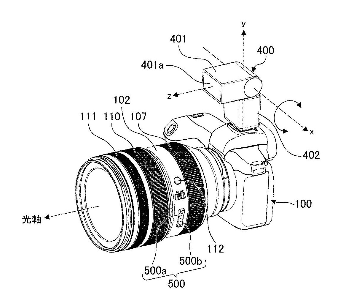
In the above image, Canon describes buttons 500a and 500b as changing the rotational angle of the flash.
The operation button 500 is a seesaw switch held in the fixed cylinder 102 so as to be movable in the plane orthogonal to the optical axis. The operation button 500 has an upper button 500a and a lower button 500b, and when the upper button 500a is pressed in a direction substantially orthogonal to the optical axis, an up switch provided inside the lens barrel is turned on. When the lower button 500b is pressed in a direction substantially orthogonal to the optical axis, the down switch provided inside the lens barrel is turned on.
The up switch and the down switch are electrically connected to the main board 114 via a flexible board. When it is detected that the upper button 500a or the lower button 500b is pressed, a second drive signal is used as rotation instruction information for the strobe light emitting unit 401 of the strobe device 400 to perform a rotation operation around the x-axis for tilt operation. Is generated. The second drive signal is transmitted from the main board 114 to the camera body 100 via the contact block 115. The camera body 100 receives the second drive signal and processes it by the microcomputer to generate the first drive signal.

In the above diagram, Canon uses a touch panel 600 to adjust the flash direction.
It's a pretty clever idea, and while I'm not sure it would ever get into an actual product, I love the fact that Canon looks to push the boundaries to what we can do when our eyes are up to the viewfinder.
Japan Patent Application 2022-003372

Richard CanonNews
Richard has been using Canon cameras since the 1990s, with his first being the now legendary EOS-3. Since then, Richard has continued to use Canon cameras and now focuses mostly on infrared photography. Richard is the founder and editor of CanonNews since 2017, and has worked as a writer on CanonRumors and other websites in the past.
Other posts by Richard CanonNews